
Optical and combined optoelectric cable terminations
Description
The main application of these products is use as a part of geological and geophysical sea complexes, in towing operations, work in hydro- acoustic systems, communication lines, depth antennas, including products for military use when power conductors are combined with optic fibre channels for transfer of information in a single cable.
Commutation of cable conductors with block equipment is performed inside of the body of a device. As a rule, pressure seals are used in case of commutation of optic fibre cbles and combined optoelectric cables.
Optical and combined optoelectric cable terminations and pressure seals designed for connection of cables containing optic and electric conductors to equipment operated in any liquid area under pressure up to 60 MPa. Different versions of the pressure seals provide connecting 1 up to 12 optical fibres and 1 up to 6 electrical conductors with operational voltage up to several kilovolts.
The terminals, hermetic in radial and longitudinal direction, protect connected equipment against flooding when cable sheath is damaged or a cable breaks.
Load terminations produced with the pressure seal or separately. The methods of their manufacture and installation are almost the same because performance of the load termination depends mainly from a structure of the cable and a type of reinforcing element. Typically, a steel wire or high-strength threads are used as reinforcing element. If the cable receives little load, the load termination can be connected directly to the sheath of cable.
Specifications
Structure of designation of pressure seals to order:
|
Terminal (НКОВх/х-х) |
Н |
К |
О |
В |
х |
/x |
- х |
|
1 |
2 |
3 |
4 |
1 – combined optic fibre cable terminal
2 – number of connected optical fibres of cable
3 – number of connected electric conductors of cable
4 – serial number of development
The terminals designed for a specific type of optoelectric cable with account of type of reinforcement element, sheath material, operating depth, connecting dimensions of a customer.
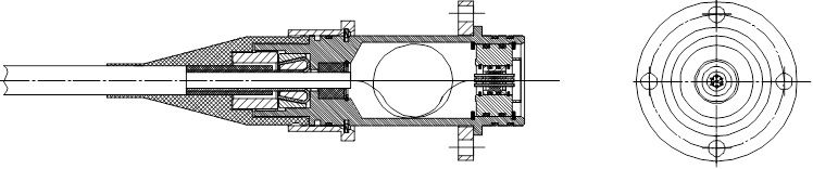
Fig. 1 – Typical design of cable termination
|
Diameter of body D, mm, not over |
50 - 90 |
|
Length L, mm |
150 - 250 |
|
Weight, kg, not over |
|
|
Material |
Steel 12Х18N10Т, АМG-5, Titanium PT-3V, glass-plastic |
|
Maximal breaking load, kN |
Depending type of cable |
|
Maximal operating pressure, kg/cm² |
Depending of requirements up to 500 kg/см² |
|
Material of cable sheath |
Polyethylene, polyurethane, TEP, PVC |
|
Reinforcing element |
Steel wire, thread Kevlar, without load termination |
|
Way of seal with equipment |
Rubber rings on cone, radial, face, combination of radial and face rings |
|
Connecting elements |
Flange, blocks |
|
Number of electric conductors |
1 - 6 |
|
Number of optic conductors |
1 - 6 |
|
Maximaloperatingvoltage, V |
On requirements of customer 3000 V |
|
Maximal current on conductor, А |
On requirements of customer up to 25 А |
All optical fibres coming from pressure seals have protective buffer with diameter 0,9 mm. On request of a customer, fibres can have an additional sheath with diameter up to 3 mm armoured by threads “Kevlar” and optical connectors.
Length of optical and electrical conductors will be specified by an order.
Detailed information about specific type of pressure seals you can find in catalogue “Pressure seals and sea bed modules”
It is possible to order cable terminals with parameters different from indicated in the catalogue.