
Optoelectric logging cables
Description
The new group of logging armoured cables with informational channels is made of single or several optical fibers inside of piped insulated copper conductors that serve as current conductor. This group of cables appeared because it became necessary to transmit big portions of information that was not possible to make on base of traditional design solutions.
The cables with optical fiber communication channel have much better characteristics comparing traditional cables on attenuation of signal and interference protection. It makes possible realize such technologies as teleinspection of wells, vertical seismic logging of wells with instruments of new generation, work with deepwater lowered equipment.
Optic fiber cables have metallic pipe as sheath of module protecting optical fiber. It guarantees operation of the cable by high pressure, torsional strain, bending and elongation.
Material of the pipe can be used as a current conductor because it insulated; it also can serve as an electrical communication channel allowing use of standard geophysical instruments.
Load carrying optic fiber cables are produced also with outer cover of armoured sheath made of two winds of wires in different direction with fill factor 0,4-0,6 and filled with polymer material.
Specifications
|
|
| Figure 1 – Optic cable with single communication channel made of 1-
optic fiber | Figure 2 – Optic cable with 3-communication channel and 3- copper conductors with armoured sheath |
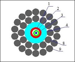
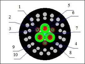
Main parts of design
1- optic communication channel;
2- hydrophobic filler;
3- copper pipe;
4- sheath
5- current conductor;
6- insulation;
7- filling element;
8,9 – load carrying element from steel high-carbon wire;
10 - outer sheath.
Table 1 – Specification of optic fiber armoured cables
|
Type of cable |
Breaking strength not less |
Number and type of optic fiber |
Resistance of conductor |
Design of armour |
Outer diameter of cable |
Weight 1 km |
|
|
kN |
n |
Оhm/km |
nxd,mm |
nxd,mm |
mm |
kg/km |
|
|
|
4 |
1 - ООВ |
25,2 |
12x0,8 |
4,3 |
70,0 |
|
|
|
8 |
2 - МОВ |
20,0 |
12x0,9 |
18x0,9 |
6,4 |
170,0 |
|
|
55 |
3 - ООВ |
10,0 |
19х0,9 |
19х1,25 |
9,4 |
350,0 |
|
|
60 |
3 - ООВ |
15,0 |
14х1,1 |
17х1,3 |
15,6 |
440,0 |
|
|
80 |
6 - ООВ |
1,5 |
24х1,1 |
24х1,3 |
25,0 |
1300,0 |
Table 2 Specification of optic fiber
|
Properties |
Single mode OF |
Multi- mode OF |
||
|
Standard |
Dispersion shifted |
50/125 |
62,5/12 |
|
|
Attenuation, dB/km |
||||
|
On wave length 850nм |
- |
- |
3,2 |
3,7 |
|
On wave length 1300nm |
- |
- |
1,1 |
1,4 |
|
On wave length 1310nm |
0,7 |
- |
- |
- |
|
On wave length 1550nm |
0,7 |
0,7 |
- |
- |
|
Chromatic dispersion, ps/nm/km |
||||
|
On wave length 1310nm |
3,5 |
- |
- |
- |
|
On wave length 1550nm |
18 |
2,7 |
- |
- |