
Mini-coiltubing operations
Description
Mineral deposits that produce most of gas and oil in Russia are in operation already 20-50 years. They came to 4-5 stage of development. In this situation, the most important factor maintaining production is the overhaul of wells and increase of oil output of layers. The company OAO “Surgutneftegas” is performing a large programme of a well overhaul and increase of oil output and succeed not only to maintain production but augment it 5-10% a year. It is necessary to notice that these results were achieved also because of massive use of coiltubing technologies. “Surgutneftegas” has 27 coiltubing assemblies –more than any other company in Russia does. For comparison, OOO “Gasprom” has only 24 assemblies having number of wells 10 times more.
Features of the coiltubing technologies that offer the principle advantages:
possibility to work without personnel necessary for well overhaul with minimal time for transportation and installation;
most of wells have very low pressure in layers. Therefore, operations performed on a depression with minimal influence to the layer are most effective. This demands sealing of a wellhead during whole operation with use of a special blow out preventing equipment; it is very difficult and often cannot be implemented applying a production tube.
Further, description will be given for typical operations with use of coiltubing.
Specifications
Development of wells with gas lift by gasfluid mixtures
One of the ways to decrease counter pressure to a layer for stimulation of gas inflow is removal of the fluid filling the well with gaslift. This operation connected with lowering of additional column of pipes through which gas is supplied to the well for aeration of the fluid. The rise of the fluid performed through the well lifting pipes.
Performing operations with gaslift, except assembly necessary for work with the gas pipe, additional equipment is installed at the wellhead (Figure 1). This includes container for the nitrogen, compressor (7) to pump it and collecting tank (3), if for some reasons the pipe of production collecting system would not be possible to use.
Before starting the work, set of equipment is installed over the wellhead- preventer, wellhead sealer and transporter. Diameter of the column of flexible pipes should comply with diameter of the lifting column. This condition is necessary because hydraulic resistance of the annulus channel where mixture is lifted should be low enough. Otherwise, a so called “nitrogen cushion” is formed. For example, the flexible pipes with outside diameter 25-55 mm comply to the column of lifting pipes with diameter 73 mm
Injection of nitrogen starts immediately or by lowering of the gas pipe to 100-200 m and it will not be stopped during the whole process of stimulation of the inflow.
The nitrogen is injected with gradual increase of the volume up to 14-20 m3/min. Injection pressure is constantly controlled and increased on lowering the pipe to the fluid.
The fluid in the column of lifting pipes is aerated first. If this operation performed after work with squeezing the well, it would be as rule a salty technical water or in worst case a mud solution.
To increase foaming of the fluid and effectiveness of the process, surface- active substances can be supplied to the well.
After lowering of the flexible pipe until the level of the lower perforations, operation of the gas lifting is provided for necessary time. The process is maintained until layer fluid will start to rise through the lifting column.
Further, proceeding supply of the gas, the column is raised. Rising the column up is necessary to control fluid composition coming from the well and rate flow.
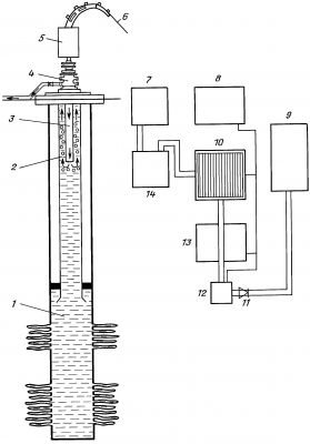
Fig.1 – Lay out of installation for gas lift:
1 – layer fluid; 2 – mixture nitrogen and layer fluid; 3 – nitrogen; 4 – equipment at wellhead; 5 – transporter; 6 –column of flexible pipes, winded on reel 10; 7 – nitrogen tank; 8 – control system; 9 – collecting tank for layer fluid; 10 – reel with flexible pipe; 11 –throttle; 12 – drive of transporter; 13 – power unit; 14 – nitrogen pumpAcid processing of layer
Acid processing is the most common operation to enhance oil production of wells or increase injectivity of injective wells. This work performed for cleaning the collector, to eliminate calmatation and increase permeability of the layer.
The operation is performed in several stages.
Normalization of the layer and cleaning of the bottomhole zone. Cleaning made by flow of a liquid (as rule- water) raised on annulus area between the production tube and a steel polymer pipe. It is necessary to maintain the rate of upcoming flow 1-3 m/s; only with this condition, solid particles are moving up.
The acid processing is performed when an acid is pushed inside of the layer under pressure 5-10 atm. higher than layer pressure.
When acid reaches the layer, it reacts with the collector. Minimal time necessary for the acid to be inside of the layer is 2-3 hours. However, if increase this time to 24 hours, the effectiveness will be higher.
Cleaning and removal products of reaction from the layer
Development of well.
Let us examine the acid procession through a jet
pump with following creation of the cyclic depression developed by the company
“EMPI-Servis” Fig.2
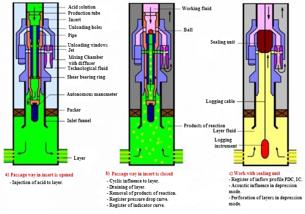
Fig. 2 – Lay out of processing through injector pump
In this arrangement, after normalization of the bottom hole, processing of the layer is performed in two stages:
1) injection of the fluid through the injector pump;
2) the ball is dropped and insert is set in depression position.
Technological fluid is supplied to the injector pump and a depression in the layer is created. On pressure drop, the collector is cleaned intensively. It is reasonable to perform cyclic effects to the layer with changing drop of pressure.
Advantage of this variant is the possibility of well development with creation of the long depression to the layer that allows its qualitative cleaning.
Selective effect on layer
Then, the pucker set in the operational mode and outer surface of chambers pressed tight to production column walls (Fig.3,b).
On the next stage of work, holes open through which cavity of the column of flexible pipes connected to the area between the packers. A necessary technological liquid is injected to this area and, if needed, a pushing liquid added. After holding well for the required time, pressure dropped, the packer set for transporting position and raised to the ground.
Design feature of a tool applied performing these operations is the packer which sealing in a transport position provides movement of the equipment inside of the column of lifting pipes with diameter 89 mm. Distance between each packer forming the double packer is selected in compliance with segment of the well which is supposed to be processed in the specific case.
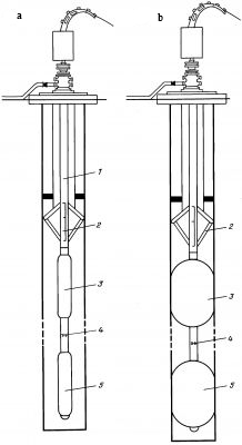
Fig.3. – Lay out of well equipment containing double pucker in transport position (a) and working position (b), and performing influence (b):
1– column of flexible pipes; 2– locator installed on column; 3– upper packer; 4–connecting pipe with holes; 5– lower packer; 6– bottomhole area of the layer being processed