
Sea optical fibre cables
Description
Trunk cables with remote supply
The cables designed for transmission of information over long distances and power supply of repeating equipment and signal amplifiers.
Specifications
|
|
| Fig.1 – Cable OK-GS27-8Е-1×0,8-84 |
Fig.2 - Cable ОК-GS33-12Е-1×0,4-240 |
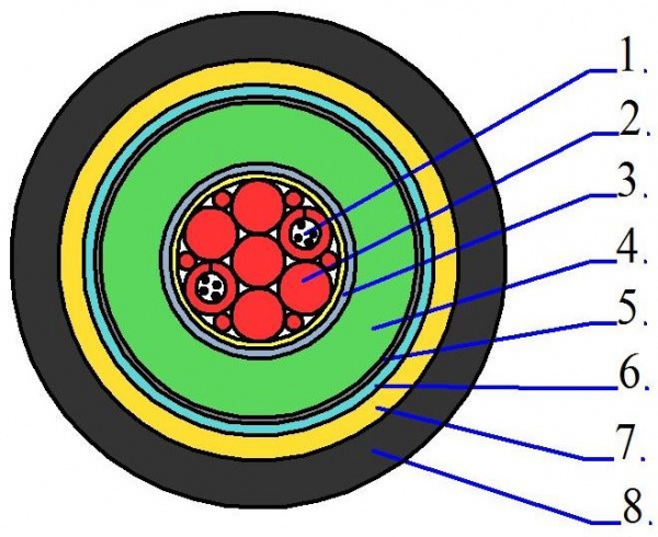
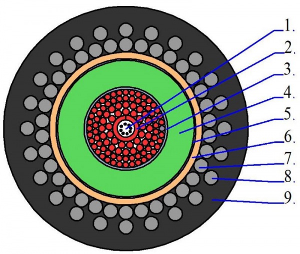
Table 1 – Mechanical and electrical characteristics of trunk cables
|
Cable type |
Breaking load, kN, not less |
Resistance of conductor, Оhм/km, not over |
Resistance of insulation , МОhm•km, not less |
Voltage, V |
Weight of cable, kg, not over |
Hydrostatic pressure, МPа |
|
ОК-GS27-8Е-1×0,8-84 |
84 |
0,8 |
20 000 |
8 000 |
570 |
50 |
|
ОК-GS32-8Е-1×0,8-84 |
84 |
0,8 |
20 000 |
8 000 |
900 |
50 |
|
ОК-GS33-12Е-1×0,4-240 |
240 |
0,4 |
20 000 |
12 000 |
2 100 |
50 |
|
ОК-GS43-8Е-1×0,8-120 |
120 |
0,8 |
20 000 |
8 000 |
800 |
50 |
|
ОК-GS47-8Е-1×0,7-50 |
50 |
0,7 |
20 000 |
8 000 |
590 |
50 |
|
ОК-GS52-8Е-1×0,7-50 |
50 |
0,7 |
20 000 |
8 000 |
590 |
50 |
|
ОК-GS53-8Е-1×0,7-32 |
32 |
0,7 |
20 000 |
8 000 |
490 |
50 |
|
ОК-GS55-8Е-1×0,4-64 |
64 |
0,4 |
20 000 |
8 000 |
940 |
50 |
|
ОК-GS58-8Е-1×0,8-120 |
120 |
0,8 |
20 000 |
5 000 |
980 |
50 |
|
ОК-GS60-8Е-1×0,4-84 |
84 |
0,4 |
20 000 |
7 000 |
710 |
50 |
|
ОК-GS61-8Е-1×0,4-90 |
90 |
0,4 |
20 000 |
7 000 |
1 086 |
50 |
|
ОК-GS62-8Е-1×0,4-140 |
140 |
0,4 |
20 000 |
7 000 |
937 |
50 |
|
|
240 |
0,4 |
20 000 |
12 000 |
2 100 |
50 |
|
ОК-GS64-8Е-1×0,7-50 |
50 |
0,7 |
20 000 |
8 000 |
590 |
50 |
|
ОК-GS65-8Е-1×0,4-64 |
64 |
0,7 |
20 000 |
8 000 |
940 |
50 |
|
|
240 |
0,4 |
20 000 |
12 000 |
2 100 |
50 |
|
КМ 8Еp-1×22,0-120 |
120 |
0,8 |
20 000 |
5 000 |
1 000 |
50 |
|
|
120 |
1,0 |
20 000 |
5 000 |
1 000 |
50 |
Communication and control cables Cables designed to provide communication between subsea objects over optical data transmission and power supply of equipment.
|
|
| Fig.3 - Cable ОК-GS21-8Е-2×4,5-28 1 – optical communication channel 2 – current conductor А 3 – insulation 4 – current conductor B 5 – insulation 6 – load carrying element 7 – sheath | Fig.4 – Cable ОК-GS57-8Е-1×4,5-25
|
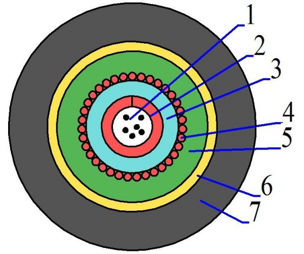
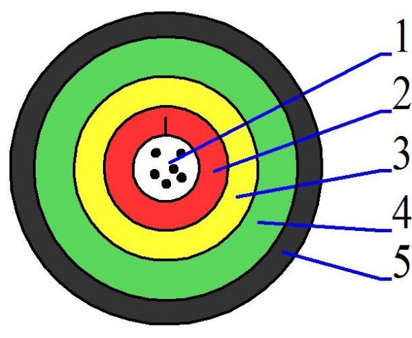
Table 2 – Mechanical and electric characteristics of communication cables
|
Cable type |
Breaking load, kN, not less |
Resistance of conductor, Оhм/km, not over |
Resistance of insulation, МОhм•km, not less |
Voltage, V |
Weight of cable, kg, not over |
Hydrostatic pressure, МPа |
|
ОК-GS21-8Е-2×4,5-28 |
28 |
4,5 |
1000 |
300 |
210 |
50 |
|
|
25 |
4,5 |
2000 |
1500 |
110 |
50 |
Combined antenna-trunk
cables
Antenna-trunk cables designed for data transmission over
long distances and they are a part of registering equipment also.

Fig.5 – Cable type КАМ 8Еm-(1×19+2×1,5+18×(2×0,2)Э)-120
1 – optical communication channel, 2 – high voltage current conductor, 3 – sealant, 4 – wind,5– insulation, 6 – screen, 7 – 1-wind of load carrying element, 8 - 2-wind of load carrying element, 9 – sheath, 10 – power current conductor, 11 – insulation of power conductor, 12 – current conductor of twisted pair, 13 – conductor insulation of twisted pair, 14 – filler, 15 – screen of twisted pair, 16 – core, 17 – sheath
Table 3 – Mechanical and electric characteristics of combined antenna trunk cable
|
Cable КАМ 8Еm-(1×19+2×1,5+18×(2×0,2)Э)-120 |
|
|
Breaking load, kN, not less |
120 |
|
Resistance of high voltage conductor, Оhm/km, not over |
1,0 |
|
Resistance of inulation of high voltage conductor, МОhm•km, not less |
20 000 |
|
Resistance of power conductor, Оhm/km, not over |
13,2 |
|
Resistance of insulation of power conductor, МОhm•km, not less |
10 000 |
|
Resistance of conductor of twisted pair, Оhm/km, not over |
89,1 |
|
Wave resistance, Оhm |
105±15 |
|
Attenuation ratio on frequency 10 МHz, dB/km, not over |
85 |
|
Weight of cable, kg, not over |
1 610 |
Load carrying cables-ropes
The cables are designed to provide a pulling force between sea surface and subsea objects and simultaneous transmission of information (through optic fibres) and current (through current conductors).
|
|
Fig.6 – Cable KG
КГ (3×4,0+2×0,5+6Е)-190-90 | Fig.7 – CableKG (6×4,0+6E)-240-90 |
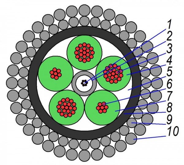
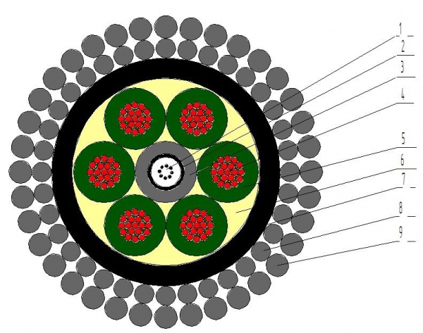
Table 4 – Mechanical and electrical characteristics of cables-ropes
|
Cable type |
Breaking load, kN, not less |
Resistance of current conductor, Оhm/km, not over |
Resistance of insulation, МОhm•km, not less |
Weight of cable, kg, not over |
Hydrostatic pressure, МPа |
|
|
200 |
4,89 50,0 |
10 000 |
1 320 |
63 |
|
КG (3×8,0+3×2Е)-240-90 |
240 |
2,45 |
10 000 |
1 850 |
63 |
|
|
240 |
4,98 |
10 000 |
1 850 |
63 |