
Wires and cables for field geophysical operations
Description
The wires are designed for installation and interconnection of measuring tools and power feeding units in different geophysical lines used in field conditions including in seismic streamers. The wires are divided in this group as power-signal and temperature and pressure resistant.
Power-signal wires is possible to classify by number and sections of conductors and tensile strength. By number of conductors, the wires can be single and double cored. Power-signal wires have the following range: 0,35; 0,5; 1,0; 2,5; 4,0 и 6,0 мм2. On tensile strength, the wires can be divided as with normal strength (copper cores) and reinforced (steel copper cores).
Specifications
Power-signal wires are made from copper and steel-copper current conductors and insulated by light stabilized low-pressure polyethylene. Design of wires and technical parameters are indicated in the table No1.
Letter notation of power-signal wire is performed the following way:
Г /G- geophysicalП/ P - wire (second letter), polyethylene insulation (last or penultimate letter) М /M –copper wires of conductor С /S– steel wires of conductorО /O– light weight
Example of notation: ГПСМПО 1,0– geophysical wire with steel copper conductor(s) with section 1,0 mm2 and insulation of polyethylene, lightweight.
Thermal and pressure resistant wires are designed to manufacture a geophysical probe cable operating at alternating voltage up to 500 V and temperature up to +200 оС.
Thermal and pressure resistant wires are made from steel-copper or copper-steel current conductors with section 1,5 mm2, insulated by copolymer propylene (+150 оС) or by fluoroplast (+200 оС) when steel and copper wires are in different winds.
Example of notation:
TBP 1,5-150-SM– thermal and pressure resistant wire with steel copper current conductor (inside wind of steel wire, outside copper wire) with section 1,5 mm2 in insulation from copolymer propylene.
TBP 1,5-200-MS– thermal and pressure resistant wire with copper-steel current conductor (inside wind of copper wire, outside steel wire) with section 1,5 mm2 and insulation of fluoroplast.
Fig.1 – Appearance of geophysical wires
Table 1 – Technical parameters of geophysical wires
|
Cable type |
Resistance of conductor, not over Оhm/km |
Resistance of insulation, not less МОhm*km. |
Calculated weight, kg/km |
|
Signal -power wires TU 16.К79-006-88 |
|||
|
GSP 1х0,35 |
98,6 |
500 |
5,3 |
|
GSP 2х0,35 |
98,6 |
500 |
10,7 |
|
GSP 1х0,5 |
68,5 |
500 |
7,8 |
|
GSP 2х0,5 |
68,5 |
500 |
15,8 |
|
GPSMP 1х2,5 |
12,46 |
500 |
34,7 |
|
GPSMP 1х4,0 |
7,7 |
500 |
49,6 |
|
GPMP 1х6,0 |
3,11 |
500 |
76,0 |
|
GPSMPO 1х1,0 |
40,0 |
500 |
17,2 |
|
GPSMPO 2х1,0 |
40,0 |
500 |
35,3 |
|
GPMP 1х2,5 |
8,05 |
500 |
35,7 |
|
GPMP 1х4,0 |
4,89 |
500 |
51,1 |
|
Wires thermal and pressure resistant TU 14172-500-41578716-01 complies TU 16-705.065-78 |
|||
|
TBP 1,5-150SM |
18,4 |
250 |
18,5 |
|
TBP 1,5-150MS |
36,8 |
250 |
16,3 |
|
TBP 1,5-200SM |
18,4 |
250 |
24,0 |
|
TBP 1,5-200MS |
36,8 |
250 |
22,3 |
|
|
|
|
Inner wind-steel wires, outside wind of copper wires |
Inner wind – copper wires, outside –steel wires |
Mixed steel-copper wind |
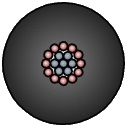


Fig.2 – Examples of geophysical wires.
Seismic cables
This type of geophysical cables is designed for seismic exploration in field conditions in communication lines of seismic stations with linear channel division, and telemetry stations at minimal operating temperature up to -50 oC.
Seismic cables classified by the following main features:
- Number of cores (pairs) – can be up to two hundred;
- Flexibility – divided in two groups: with normal flexibility (single wire current conductor) and increased flexibility (multi-wire current conductors);
- Tensile strength - alsodivided in two groups: normal strength and increased strength (cables with load carrying element).
Design of seismic cables:
Load carrying element(in cables with increased tensile strength) made of high-strength threads (SVM-thread, Armos, Kevlar) that increased cable tensile strength not affecting flexibility of the cable. Depending design of the cables, load-carrying element can be covered by sheath of thermal plastic polyurethane.
Current conductor produced in three versions:
1. Steel copper wire formed by winding of four steel galvanized wires with diameter 0,25 mm and three tined copper wires with diameter 0,25 mm. Steel-copper conductor is used for cables KS-2S и KS-3S.
2. Single wire conductor formed as self-tinned enameled wire PEVTL-1-155 with diameter 0,335 mm.
3. Multi-wire conductor formed as strand of seven soft copper wires with diameter 0,12 mm.
Insulation of copolymer propylene on current conductors.
Filler– sealing material preventing water ingress to cable. The filler is used by request of a customer.
Dividing yarn –cottonyarn of different colors serves to divide of winds. Dividing yarn is laid to the cable with number of winds not over two.
Winding – polyethylene terephthalate for fixing core of the cable.
Sheath of seismic cables produced of thermoplastic polyurethane with increase stability to abrasion, frost resistance, flexibility and resistance to mould.
|
|
|
|
Cable КS-3S – for connection of geophone to communication line of seismic stations. 1 – steel wire; 2 – copper wire; 3 - sheath. |
Cable KSTGA -16 – for communication lines with digital seismic stations of type Input/Output. 1 – load carrying element (yarn Armos); 2 – twisted pairs; 3 - sheath. |
Cable KSL 100-EM-SU –for use in seismic communication lines with linear division of channels. 2 – twisted pairs; 3 - sheath. |
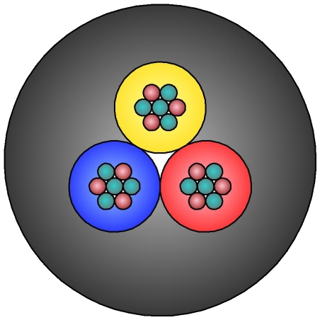
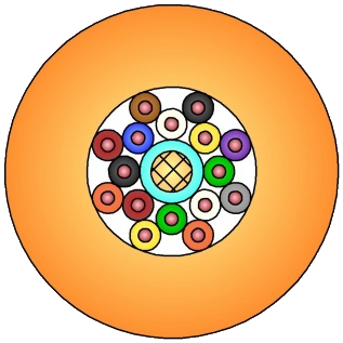
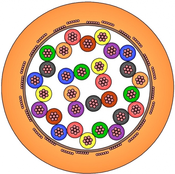
Fig. 3 – Example designs of seismic cables
Table 2 – Technical characteristics of seismic cables
|
Type |
Diameter of cable not over, mm |
Breaking load not less, kN |
Weight not over, kg/km |
Resistance of core not over, Оhm/km |
|
КSTGA-16 |
9,0 |
1,2 |
80 |
225,3 |
|
KSL56х0,08-3,5У |
17,0 |
3,5 |
215 |
247,5 |
|
КSL56х0,08-3,5У |
17,0 |
3,5 |
224 |
225,3 |
|
KSL200х0,08-45У |
19,0 |
45 |
400 |
247,5 |
|
KSL24-EМ-SU |
9,1 |
- |
86 |
225,3 |
|
KSL24-7М-SU |
9,1 |
- |
84 |
247,5 |
|
KSL40-7М-SU |
12,5 |
- |
156 |
165,3 |
|
KSL50-EM-SU |
12,5 |
- |
155 |
225,3 |
|
KSL50-7М-SU |
12,5 |
- |
146 |
247,5 |
|
KSL100-EM-SU |
15,5 |
- |
240 |
225,3 |
|
KSL100-7М-SU |
15,5 |
- |
225 |
247,5 |
|
|
15,5 |
- |
270 |
247,5 |
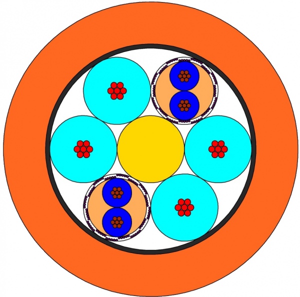
Fig. 4 – Appearance of seismic cables