Coaxial cables
Description
A screened conductor is the main feature of these cables. The screen provides good protection from external electromagnetic interference. Therefore, the cable ensures high speed and quality of data transmission over long distances and operation with television equipment. The main characteristic of coaxial cable is the impedance.
The common part in the design of these cables is load carrying element- two windings of steel armor.

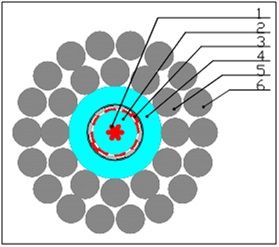
Fig. 1 Typiñal design of coaxial load carrying cable
1- copper current conductor
2- insulation of conductor
3- screen
4- sheath
5.6 –armour
The cables have different versions of screen:
a) winded flat copper tapes;
b) copper wire and polyester fiber braid;
c) braids of thin copper wires.
Specifications
Table 1 – Mechanical properties of load carrying armored coaxial cables
|
Type of cable |
Breaking strength |
Design of armor Inner/outside |
Elongation |
Max.operating temperature |
Outer diameter of cable |
Weight in air |
Weight in fresh water |
|
kN |
nõd(mm) / nõd(mm) |
m/km/kn |
oÑ |
mm |
kg/km |
kg/km |
|
|
|
30 |
12õ0,85/18õ0,85 |
0,52 |
90 |
6,25 |
156 |
126 |
|
|
50 |
12õ1,2/18õ1,2 |
0,30 |
90 |
8,7 |
310 |
251 |
|
|
55 |
15õ1,1/18õ1,3 |
0,22 |
90 |
9,3 |
353 |
285 |
|
|
55 |
18õ1,1/24õ1,1 |
0,22 |
90 |
10,25 |
391 |
308 |
|
|
55 |
18õ1,1/24õ1,2 |
0,22 |
90 |
10,25 |
395 |
312 |
|
|
70 |
24õ0,95/24õ1,2 |
0,18 |
90 |
11,4 |
453 |
351 |
|
|
150 |
24õ1,35/24õ1,75 |
0,10 |
90 |
16,5 |
921 |
707 |
|
ÊGP 1-190 |
190 |
28õ1,55/34õ1,55 |
0,10 |
90 |
20,0 |
1226 |
912 |
Table 2 – Electrical specifications of load carrying armored coaxial cables
|
Type of cable |
Section of central conductor |
Resistance of central conductor not over |
Section of screened conductor |
Resistance of screened conductor not over |
Resistance of insulation not less |
Impedance notless |
Attenuation ratio not over* |
|
ìì2 |
Ohm/km |
mm2 |
Ohm/km |
ÌÎhm*km |
Îhm |
Db |
|
|
|
0,20 |
89,1 |
0,20 |
113,1 |
5000 |
35 |
65,0 |
|
|
0,35 |
57,0 |
0,35 |
59,5 |
5000 |
40 |
42,5 |
|
|
0,50 |
40,5 |
0,50 |
39,0 |
5000 |
40 |
38,0 |
|
|
1,0 |
19,8 |
1,5 |
11,6 |
10000 |
40 |
27,5 |
|
|
1,5 |
13,2 |
1,5 |
11,6 |
10000 |
30 |
29,5 |
|
|
2,0 |
9,97 |
2,0 |
9,97 |
10000 |
40 |
19,2 |
|
ÊGP 1-150 |
2,0 |
9,97 |
3,5 |
6,50 |
20000 |
50 |
15,5 |
|
|
4,0 |
4,89 |
4,0 |
4,89 |
20000 |
50 |
14,0 |
* Attenuation ratio is for frequency 5 MHz
