
Onboard and outboard optic fibre cables
Description
Onboard cables of small diameter with single mode and multi-mode optical fibres are designed for stationary laying of board optic fibre systems for transmission of information and communication of onboard equipment.
Specifications
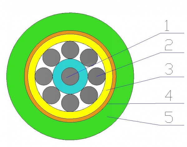
Fig.1 – CabletypeОК-BS01-1Е-1,0
1 – optic fibre
communication channel, 2 – reinforcing
element, 3 – armouring, 4 – substrate, 5 – sheath
Table 1 – Main parameters of onboard cables
|
Cable type |
Fibre type |
Number of optical fibre in cable, pc. |
Attenuation, dB/km, not over |
Diameter, mm |
Weight, kg/km, not over |
|
ОК-BS01-1Е-1,0 |
Single mode |
1 |
Length wave 1550 nm – 1,0 |
1,80±0,1 |
4,3 |
|
ОК-BS02-1M-3,0 |
Multi- mode |
1 |
Length wave 1310 nm – 3,0 |
1,80±0,1 |
4,3 |
Outboard
cables designed for operation on shelf providing communication with portable ship equipment and outboard instruments, for installations, stationary laying inside of compartments, between compartments, outboard deployment through high-pressure seals.
The following cable
types are produced:
- ОК-NS01 иОК-NS02 – optical cable
for outboard deployment, design number 01 и 02, with optic modules
(ОМ) under polymer sheath;
- ОК-NS03 иОК-NS04 – same but
with design number 03 and 04, with optical module in metallic sheath. ExamplesofdesignationofcablestypeОК-NS01 with two
single mode optical fibre by order and in documents of another product:
Cable ОК-NS01-2Е
|
|
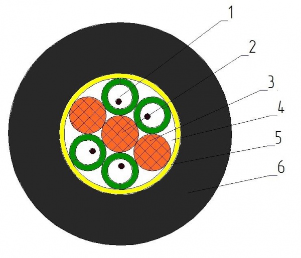
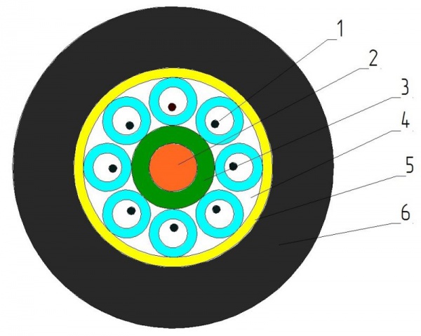
Fig.2 - Cables ОК-НС with number of OF 2 to 6 Fig.3 - Cables ОК-NS with number of optical fibre 8
1 – optic fibre communication channel, 2 – central load carrying element, 3 – insulating cord, 4 – sealant, 5 – wind, 6 – sheath
Table 2 – Main characteristics of optical cables for outboard deployment
|
Cable type |
Number of optical fibres, pc. |
Type o fibre |
Breaking load, kN, Not less |
Outer diameter, mm |
Weight, kg/km,not over |
|
|
2,4,6 |
Single mode Multi-mode |
1 |
9,0±0,2 |
126 |
|
|
8 |
Single modeMulti-mode |
1 |
10,0±0,2 |
157 |