
Optical fibre cables for general applications
Description
Communication optical cables are produced according technical conditions TU 3587-023-24118545-2012 and intended for use in unified telecommunication network of Russian Federation.
Depending of type and performance, the cables can be deployed:
- underground including mechanized way;
- on river crossings, deep water reservoirs, in swamps;
- on bridges, overpasses in cable conduits, in blocks, in special tubes;
- on aerial lines, aerial contact lines of railway, on power poles;
- inside of buildings on walls in vertical and horizontal cable ways, in
tunnels and collectors, in subway tunnels.
Dependingconditionsofinstallation, the cables are operated by temperatures:
- suspended cables - from -60 °С up to +70 °С;
- cables installed on bridges, overpasses
- from -50°С up to +50 °С;
- underground and subsea cables - from -40 °С up to +50 °С.
The cables of
each type produced with different type and number of a cores and optical
fibres.
A standard notation of a special type of the cable contains twelve positions
which can be completed by other two (13 and 14).
A structure of notation of the cable should have:
| ОК | – | В | П | Т | – | М | 4 | – | 24 | Е1 | – | 2х0,35 | – | 10/0,4 | – | Д | – | Х | |
| 1 | – | 2 | 3 | 4 | – | 5 | 6 | – | 7 | 8 | – | 9х10 | – | 11/12 | – | 13 | – | 14 |
Specifications
Table 1- Explanation of positions
|
Position |
Property |
Possible meaning |
Explanation |
|
1 |
Cable type |
ОК |
Optical cable |
|
2 |
Type of installation |
В З Г |
- aerial - underground, on bridges and overpasses - underwater, in soil with freezing deformations |
|
3 |
Type of inner sheath |
П А |
- polyethylene - aluminium-polyethylene |
|
4 |
Type of reinforcing element |
- Л С Д Т Тс |
- without additional outside covers - with corrugated steel tape - with armour of steel wires - with armour of steel plastic bars - with reinforcing elements of high-modulus yarn - with reinforcing elements based on glass fibres |
|
5 |
Type of core |
М Т |
- module with dielectric central reinforcing element - tube (centralopticalmodule) |
|
6 |
Number of optical modules in core, pc. |
1-12 1 |
- core of module design - core with central optical module |
|
7 |
Number of optical fibres in cable, pc. |
1-576 1-48 |
- for cables with core of modular design - for cables with core and central optical module |
|
8 |
Fibre type |
Е1 Е2 Е3 Е4 Е5 Е6 МГ1 МГ2 |
- single mode with not shifted dispersion - single mode with minimized losses - single mode with additional transparency window - single mode with shifted dispersion - single mode with non zero shifted dispersion - single mode resistant to flexures - multi-mode with core diameter 50 mm - multi-mode with diameter of core 62,5 mm |
|
9 |
Section of current conductor, mm2 |
0,2-6,0 |
- section of current conductor 0,15 up to 8,0 |
|
10 |
Static tensile force, kN |
1,5-5,0 7,0-50,0 3,0-50,0 3,0-15,0 7,0-15,0 20,0-60,0 7,0-90,0 35,0-120,0 40,0-200,0 |
- types ОК-ВП-М, ОК-ВА-М, ОК-ЗПЛ-М - types ОК-ЗПС-Т, ОК-ЗАС-Т - types ОК-ВПТ-М - typesОК-ВПТс-М - types ОК-ЗПД-М, ОК-ЗПД-Т - types ОК-ГПД-Т - types ОК-ЗПС-М, ОК-ЗАС-М - types ОК-ГПД-М - types ОК-ГПС-М, ОК-ГАС-М, ОК-ГПС-Т, ОК-ГАС-Т |
|
11 |
Permissible crashing load, kN/cm |
0,4-0,7 0,4-1,0 0,7-1,0 0,7-1,5 1,0-1,5 |
- types ОК-ВП-М, ОК-ВА-М, ОК-ВПТс-М, ОК-ВПТ-М - марки ОК-ЗПС-М, ОК-ЗАС-М, ОК-ЗПЛ-М, - марки ОК-ЗПД-М, ОК-ЗПД-Т, ОК-ЗПС-Т, ОК-ЗАС-Т - марки ОК-ГПД-М, ОК-ГПС-М, ОК-ГАС-М - марки ОК-ГПС-Т, ОК-ГАС-Т, ОК-ГПД-Т |
|
12 |
Outside sheath |
Н Т Д |
- flame retardant - outer sheath from thermal resistant polyethylene - outer sheath of arc-resistant polyethylene |
|
13 |
Operating temperature range |
Х |
- for cables operated outdoor, от -60 °Сдо +70 °С |
|
|
|
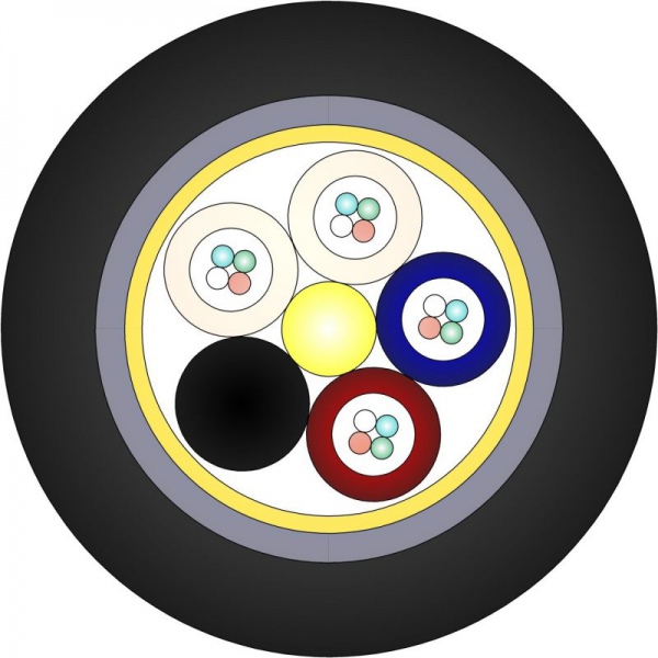
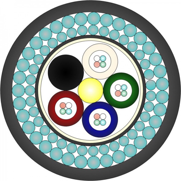
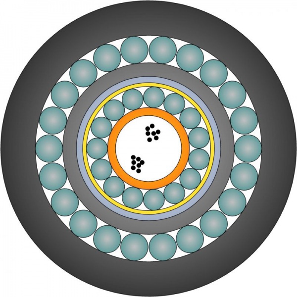
| Fig.1 – Cable type ОК-ВП-М | Fig.2 – Cable type ОК-ГАС-М | Fig.3 – Cable type ОК-ГПС-Т |
Declarations of conformance from Federal Communication Agency for optical communication cables produced according TU 3587-023-24118545-2012 are received.
Table 2 – Main
mechanical and climatic characteristics of communication cables
|
Type of cable |
Static tensile force, kN, not less |
Crashing loads, kN/100 mm, not less |
Impact force, Дж, not less |
Maximal operating temperature, ºС |
Declaration of conformity |
|
ОК-ВП-М |
1,5 |
3,0 |
5 |
от -60 до +70 |
|
|
ОК-ВА-М |
1,5 |
3,0 |
5 |
от -60 до +70 |
|
|
ОК-ВПТ-М |
3,0 |
3,0 |
5 |
от -60 до +70 |
|
|
|
3,0 |
3,0 |
5 |
от -60 до +70 |
|
|
ОК-ЗПС-М |
7,0 |
7,0 |
10 |
от -50 до +50 |
|
|
ОК-ЗАС-М |
7,0 |
7,0 |
10 |
от -50 до +50 |
|
|
|
2,5 |
4,0 |
10 |
от -50 до +50 |
|
|
ОК-ГПС-М |
20,0 |
10,0 |
20 |
от -50 до +50 |
|
|
ОК-ГАС-М |
20,0 |
10,0 |
20 |
от -40 до +50 |
|
|
ОК-ГПД-М |
7,0 |
7,0 |
10 |
от -50 до +50 |
|
|
ОК-ЗПС-Т |
7,0 |
7,0 |
10 |
от -50 до +50 |
|
|
ОК-ЗАС-Т |
7,0 |
7,0 |
10 |
от -50 до +50 |
|
|
|
2,5 |
4,0 |
10 |
от -50 до +50 |
|
|
|
20,0 |
10,0 |
20 |
от -50 до +50 |
|
|
ОК-ГАС-Т |
20,0 |
10,0 |
20 |
от -40 до +50 |
|
|
ОК-ГПД-Т |
7,0 |
7,0 |
10 |
от -50 до +50 |